
In chemical, pharmaceutical, electroplating, and hydrometallurgical operations, drip leakage at pump and valve seals exposed to strong acids or alkalis remains a chronic maintenance headache. Even a minor weep wastes media, attacks equipment foundations, and creates serious safety and environmental risks. Field experience consistently shows the root cause is rarely the pump or valve body itself—it’s the gasket material failing under aggressive chemical conditions.
This article delivers root cause analysis, emergency countermeasures, material upgrade logic, and standardized installation and maintenance practices. It maps a complete, field-ready path to replace traditional asbestos gaskets with PTFE gaskets, achieving a permanent corrosion-resistant seal.
1. Pump and Valve Sealing Demands
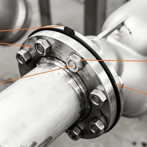
Pumps (mostly centrifugal, magnetic drive, and diaphragm types) and valves (ball, butterfly, globe, etc.) in corrosive service pressurize, meter, isolate, and regulate the fluid. At casing, flange, and bonnet joints, static seals are formed by gaskets to prevent pressurized, highly penetrative chemicals from escaping across the flange faces.
In acid and alkali environments, a gasket must deliver four critical properties:
Chemical inertness – withstands long-term corrosion, swelling, and degradation without material change.
Sealing stress adaptability – compresses and recovers sufficiently under bolt preload to fill flange micro-irregularities.
Temperature-pressure capability – maintains seal integrity under operating pressure fluctuations without relaxation failure.
Regulatory compliance – free of hazardous constituents (e.g., asbestos fibers), meeting occupational health and environmental standards.
Wrong gasket selection or poor installation quickly causes interface leakage that turns into frequent drip issues shortly after startup.
2. Root Causes of Persistent Drip Leakage
2.1 Chemical Attack and Permeation of the Gasket Material
Traditional asbestos gaskets offer some heat resistance, but their structure relies on asbestos fibers and a binder. Strong acids (especially concentrated sulfuric and hydrochloric acid) break down the binder’s molecular chains and cause swelling. In hot, concentrated alkalis, the binder undergoes saponification and degradation—eventually destroying the seal. Once corrosion starts at the inner edge, the media wicks along fiber gaps, creating micro-channels that develop into a constant drip. Worse, the loose fibrous structure of asbestos gaskets leads to “capillary permeation”: even without visible damage, fluid slowly seeps through the gasket body, causing flange face sweating and dripping.
2.2 Insufficient Compressibility/Recovery and Stress Relaxation
Under sustained heat and bolt load, asbestos gaskets creep and relax. Thickness decreases and contact stress drops steadily. When startup/shutdown cycles or temperature swings cause micro-movements of the flange, the gasket cannot rebound to compensate, and a leak path opens. Strong acid and alkali processes often involve temperature fluctuations—dilution exotherms, jacketed reactor temperature changes—that accelerate this failure. Repeated retightening of asbestos gaskets only gives temporary relief; it never eliminates the root cause.
2.3 Improper Installation Practices
Incomplete cleaning of flange faces leaves old asbestos gasket fragments, corrosion pits, or scratches that disrupt the sealing line. Wrong bolt tightening sequence causes uneven gasket compression. Excessive compression crushes the asbestos gasket, destroying its resilience. These human errors cause new asbestos gaskets to leak shortly after installation.
2.4 Legacy Material Selection
Many older lines were originally designed with asbestos gaskets, without fully accounting for the permeation and corrosive attack of strong chemicals. Some plants fail to match gasket material accurately to actual pH, temperature, and pressure. As a result, asbestos gasket service life falls far short of expectations, and drip leakage becomes the norm.
3. Emergency Response to Sudden Leak Incidents
When a drip leak is spotted at a pump or valve flange, follow a tiered response to prevent escalation.
(1)Minor Weep (moisture only, no continuous dripping)
- Confirm the leaking medium using pH paper or a portable detector tube.
- If the system allows, attempt bolt retightening in a diagonal sequence, turning no more than 1/6 turn per step. Use a feeler gauge to check if the flange gap stays even. Caution:tightening a chemically attacked asbestos gasket may stop the leak only momentarily, or even crush the gasket locally and accelerate leakage. This is strictly a temporary measure.
- Set up drip diversion or splash shields to protect personnel.
- Log the leak location and operating conditions, and schedule a shutdown to replace the asbestos gasket with a PTFE gasket.
(2)Visible Drip or Continuous Flow
- Immediately isolate the area; initiate an emergency shutdown if necessary.
- Close upstream valves, drain the pump and piping, flush to a neutral pH, and depressurize to atmospheric.
- Neverloosen flange bolts while the system is pressurized, hot, and filled with chemicals. Doing so can release a high-pressure acid or alkali spray, causing severe chemical burns.
- Wear full chemical-protective PPE and establish a safety perimeter.
- Open low-point drains, confirm the line is empty, then disassemble per standard procedure. Remove the failed asbestos gasket and install a PTFE gasket.
- After the emergency gasket change, run the equipment at low load for 15–30 minutes and inspect the seal point. Only return to normal operation when no leaks are observed. Add this joint to the priority inspection list.
Permanently solving acid and alkali pump/valve seal drip leakage requires upgrading the gasket material from asbestos to a PTFE-based structure. The corrosion resistance and overall performance of PTFE gaskets are a perfect match for these conditions.
4.1 Asbestos Gasket vs. PTFE Gasket Performance
| Performance Attribute | Asbestos Gasket | PTFE Gasket |
| Chemical Resistance | Poor – binder degrades in strong acids, saponifies in hot alkalis; loose fiber structure causes severe permeation | Excellent – virtually inert to all strong acids, alkalis, and organic solvents; dense material, zero permeation |
| pH Range | Limited to weak acids/alkalis, generally safe only between pH 4–10 | Full pH 0–14 range |
| Temperature Limit | Typically ≤200 °C | -200 °C to 260 °C |
| Permeability | High – capillary wicking through fibers is common | Extremely low – inherently non-porous, no capillary channels |
| Compressibility & Recovery | Moderate, but significant stress relaxation at elevated temperatures | Can be engineered with fillers (glass fiber, graphite) to resist creep; modified PTFE gaskets offer excellent recovery |
| Health & Environment | Contains asbestos fibers, banned in many countries, generates carcinogenic dust during handling | Non-toxic, fiber-free; meets FDA, USP, 3-A and other standards |
| Seal Life | Short – frequent retightening and drip leakage in acid/alkali service | Long – with proper installation, can match or exceed overhaul intervals |
| Material Stability | Single-use, ages quickly | Maintains long-term chemical stability, does not age rapidly |
4.2 PTFE Gasket Advantages
Corrosion Resistance: PTFE gaskets are chemically inert to strong acids and alkalis. Unlike asbestos gaskets that rely on attack-prone binders, they do not swell or degrade in concentrated sulfuric acid or sodium hydroxide, eliminating the corrosion leakage pathway at the source.
Zero-Permeation Seal: Asbestos gaskets are loosely fibrous, allowing media to creep through capillaries and cause micro-leaks. PTFE gaskets are dense and pore-free—completely stopping this phenomenon. This is especially critical for highly penetrative media like hydrochloric acid or wet chlorine. Flange exteriors stay permanently dry.
High Recovery & Low Relaxation: Filled with glass fiber, graphite, or used in expanded form, PTFE can overcome cold-flow creep. When process fluctuations cause micro-movements at the flange face, the gasket rebounds to maintain sealing stress, ending the constant retightening cycle that plagues asbestos gaskets.
Lifecycle Compliance & Cost Savings: Replacing asbestos gaskets eliminates the occupational exposure risk to carcinogenic dust and special waste disposal costs. The extended seal life of PTFE gaskets drastically reduces unplanned downtime, media loss, and labor. The total long-term cost is far lower than repeatedly changing asbestos gaskets.
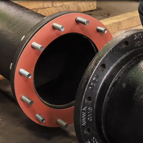
4.3 Recommended PTFE Gasket Types
Option 1: Glass-Fiber Filled PTFE Gasket
Media: All strong acids and alkalis (except hydrofluoric acid), pH 0–14.
Temperature: -200 °C to 260 °C; especially suited for pump and valve flanges with frequent temperature swings.
Pressure: Covers most industrial pump and valve classes up to PN16.
Applications: Centrifugal pump casings, valve bonnets, pipe flanges—all standard acid/alkali joints.
Option 2: Expanded PTFE Gasket
Media: All strong acids, alkalis, and ultra-pure chemicals; chemical inertness identical to virgin PTFE.
Temperature: -200 °C to 260 °C.
Pressure: Ideal for low bolt loads, fragile flanges (glass-lined, enameled), and sealing faces with minor scratches or corrosion pits.
Applications: Glass and enamel flanges, non-metallic pump casings, and equipment where damaged sealing faces have caused asbestos gaskets to repeatedly leak with no resolution.
5. Installation Guide – Standardized Procedure from Removal to Replacement
Step 1: Preparation
- Perform lockout/tagout; verify the pump/valve is de-energized, drained, flushed, and at atmospheric pressure.
- Gather dedicated tools: torque wrench, brass or aluminum scraper (to avoid scoring the flange face), non-metallic brush, stainless steel wire brush, lint-free cloths, clean solvent, and the new PTFE gasket (confirm type, size, and integrity).
- Wear full chemical-protective PPE.
Step 2: Disassembly and Old Gasket Removal
- Loosen all bolts symmetrically in multiple passes, no more than 1/4 turn per pass. Watch for binding.
- Remove bolts and nuts. Soak heavily rusted fasteners in penetrant; never force them by hammering.
- Use only soft-metal scrapers—never carbon steel scrapers or chisels—to carefully remove old asbestos gasket residues. Corroded asbestos gaskets tend to stick to the flange face; scrape thoroughly. Clean with a non-metallic or fine brass brush. Do not use abrasive discs or power wire brushes, which can destroy the flange serration finish or cause scratches.
- Wipe the sealing face with a lint-free cloth dampened with solvent, followed by a dry cloth. Visually inspect: no pits, no through-scratches, no damaged serrations. Surface roughness Ra should be 3.2–6.3 µm. If corrosion pits or sealing face damage are found, repair or replace the flange.
Step 3: Installation and Inspection
- PTFE gaskets generally require no additional sealant (unless specified by the manufacturer or where flange condition is poor). Keep the gasket and flange face clean and dry.
- Place the PTFE gasket gently between the flanges. Ensure it sits fully on the sealing face and is centered on the bolt circle. Do not use sharp tools to force it into position.
- Check flange parallelism: use a feeler gauge at a minimum of four equally spaced points around the circumference. The gap difference should not exceed 0.5 mm. If there is a gap mismatch or offset, realign the piping or pump support.
Step 4: Bolt Tightening (Three-Step Torque Method)
Lubricate bolt threads and nut bearing surfaces with an acid/alkali-resistant anti-seize compound to ensure accurate bolt load.
Step 1 – Hand-tighten & uniform contact: Hand-tighten all nuts. Then, using a standard wrench, lightly tighten in a diagonal sequence until the gasket makes uniform contact and the flange gap is roughly equal.
Step 2 – 30% target torque: Using a torque wrench, tighten all bolts in a diagonal, multi-pass sequence to approximately 30% of the final target torque.
Step 3 – 60% → 100% target torque: Continue the diagonal, even-loading pattern, stepping up to 60% and then to 100% of target torque. After each torque level, make a final pass in the same sequence to verify all bolts.
Step 4 – Verification: Measure flange gap uniformity with a feeler gauge. The deviation should not exceed ±20% of the average gap. Target torque values are based on gasket type, bolt grade, and flange standard, or the gasket manufacturer’s recommendation.
Step 5: Post-Installation Documentation
Record the PTFE gasket model, batch, installation torque, date, and installer name for traceability.
6. Maintenance and Inspection Protocols
Routine Walk-By Inspections (Operators)
- Every shift, visually check pump and valve seal areas for weeping, dripping, or crystalline deposits.
- Use pH paper or fixed probes to detect acidity/alkalinity in the air below the flange gap.
- Verify that bolt protective caps are in place to prevent external corrosion from compromising bolt strength.
Periodic Retightening and Evaluation (Maintenance Team)
- 24–48 hours after initial installation, with the system at ambient temperature and no pressure, retighten all bolts to the target torque using the same diagonal sequence. PTFE gaskets undergo minor creep relaxation in the early stage; this retorque compensates for it.
- After 500 operating hours or one month, recheck bolt torque and bring back to target. Thereafter, verify torque every 3–6 months. If multiple bolts show torque loss, investigate the root cause.
- During major overhauls, disassemble and inspect the gasket. A PTFE gasket should show no cracks, extrusion, permanent deformation, or bonding to the flange. Slight discoloration at the inner edge from media contact without corrosion pitting is normal—the gasket can be reused. If radial permeation paths along the sealing line are visible, replace the gasket.
Digital Inspection Records
Integrate seal point checks into a digital patrol system. Use torque witness marks—permanent position marks on bolt, nut, and flange—to visually track loosening trends and prevent missed inspections.
7. Common Industry Pitfalls and How to Avoid Them
Pitfall 1: Substituting Low-Grade Recycled PTFE Sheet
The market is flooded with cheap PTFE boards made from recycled resin and low filler content. They have low density and extremely poor creep resistance—seal life can be even shorter than asbestos gaskets. Always specify virgin PTFE or properly filled/modified grades from reputable suppliers, and require chemical compatibility data.
Pitfall 2: Neglecting the Bolt System
Original asbestos gasket installations often used higher bolt preloads. When switching to lower-stress PTFE gaskets, severely corroded or damaged bolt threads make it impossible to control preload accurately. Replace with high-strength stainless steel fasteners and use anti-seize lubricant.
Pitfall 3: Directly Using PTFE Gaskets in Grooved or Male/Female Flanges
Asbestos gaskets were sometimes used in tongue-and-groove or male/female flange arrangements. Plain PTFE gaskets can be over-stressed and extruded in these confined geometries. If the flange configuration features a groove or recess, select filled PTFE or specially designed, dimensionally stable gaskets, and recalculate the sealing face pressure.
8. Conclusion
Eliminating frequent drip leakage from pump and valve seals in strong acid and alkali service comes down to one core action: upgrading gaskets to chemically inert, zero-permeation PTFE gaskets, backed by strictly enforced standardized installation and maintenance procedures. This upgrade path dramatically cuts unplanned equipment downtime, meets safety and environmental regulations, and delivers direct economic and safety returns for any plant.
