
Spiral Wound Gaskets — Reliable, Resilient Sealing for High-duty Flanges
What / Why — Spiral wound gaskets combine alternating windings of metal and soft filler (graphite, PTFE, or mica) to form a spring-like seal that tolerates thermal cycling, high pressure, and flange movement. They are a standard solution for ASME/ANSI and international flange systems where leakage control and durability matter.
Executive Summary
Spiral wound gaskets are a proven, versatile sealing solution for high-pressure and high-temperature flanged joints. This page explains construction variants, selection criteria (filler, centring ring, windings, metal type), installation best practices, common failure modes and downloadable datasheets to support procurement, engineering design and maintenance teams.What is a Spiral Wound Gasket?
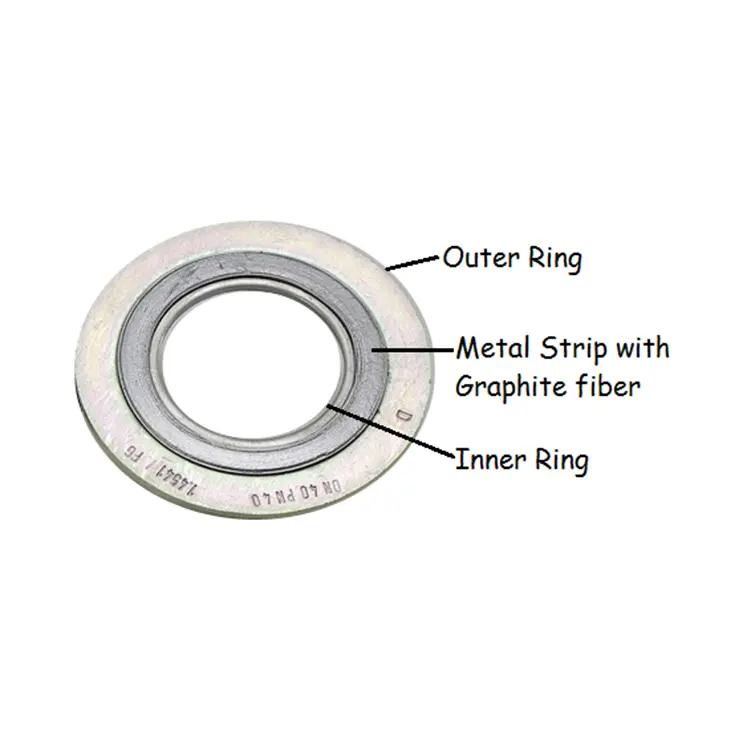
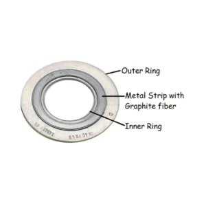
A spiral wound gasket consists of a continuous strip of metallic material wound in an open spiral with a softer filler (graphite, PTFE, mica) inserted between the windings. Optional inner and outer centring rings (metal or soft) provide flange protection, prevent overcompression and help installation alignment. The wound geometry provides springiness, allowing the gasket to recover after thermal cycles and maintain contact stress.-
 Spiral Wound Gasket
Spiral Wound Gasket With Inner Ring
-
Spiral Wound Gasket
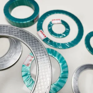
Spiral Wound Gasket Without Inner Ring
Classification — By Metal, Filler, and Configuration
By Metal (Winding)
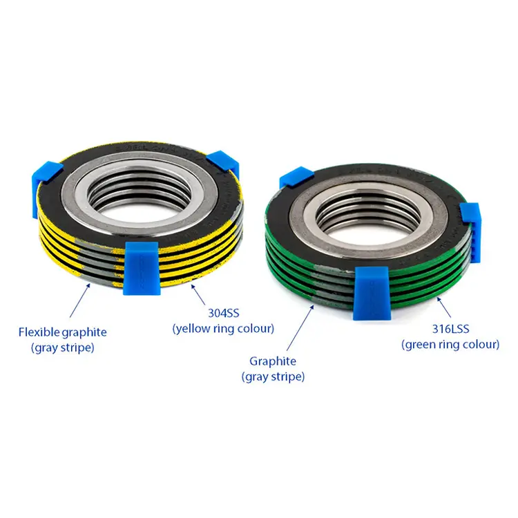
- Stainless steel (304 / 316) — common, corrosion resistant
- Inconel / Alloy (600/625) — for high temperature or corrosive services
- Soft iron or carbon steel — used when cost and compatibility permit
By Filler
- Flexible graphite — high temperature, good compressibility
- PTFE — excellent chemical resistance, low friction
- Mica or ceramic fillers — high temperature electrical insulation or specific chemical needs
By Configuration
- Standard spiral wound (no rings)
- With inner metal centring ring (protects bore & avoids inward extrusion)
- With inner and outer rings (full support & flange protection)
- ASME/EN standard sizes, RTJ-adapted versions and custom OD/ID/thickness
Selection Guide — How to Choose the Right Spiral Wound Gasket
- Identify service conditions — temperature ranges (steady and spikes), pressure class, and whether service is oxidizing.
- Choose filler — graphite for high-temp steam, PTFE for aggressive chemicals; verify chemical compatibility at concentration and temperature.
- Select winding metal — stainless for general service; Inconel or higher alloy for hot corrosive environments.
- Decide on centring rings — inner rings prevent inward extrusion on ring gaskets; outer rings protect flange faces and help with bolt loading.
- Thickness & turns — thicker gaskets and more turns improve sealing on coarse flanges but require higher bolt load; consult ASME/EN guidelines.
- Surface finish & flange class — check flange finish and rating; choose gasket class and preload accordingly.
Tip: For thermal cycling and vibration use gaskets with adequate winding turns and consider stainless steel winding with graphite filler plus inner centring ring for reliability.
Technical Parameters & Common Specifications
Typical reference values| Configuration | Filler | Typical Temp Range (°C) | Pressure Class | Common Thickness (mm) |
|---|---|---|---|---|
| SS winding / Graphite filler | Flexible graphite | -200 to 450 | ASME Class 150 — 2500 | 3 / 4.5 / 6 / 9 |
| SS winding / PTFE filler | PTFE | -200 to 250 | Up to Class 600 (check design) | 3 / 4.5 / 6 |
| Inconel winding / Graphite filler | Graphite | -200 to 650 | High pressure & temp services | 3 / 4.5 / 6 |
| Graphite winding / Mica filler | Mica/ceramic | Up to 800 (special) | High temp applications | Varies |
Common Standards & Size Ranges
| Standard | Typical Range | Notes |
|---|---|---|
| ASME B16.20 / API | Class 150 — 2500, OD/ID to fit flanges | Most common industrial spiral wound specs |
| EN / DIN | PN6 — PN640 equivalents | European flange compatibility |
| Custom | Special OD / ID / thickness | Die-cut or built-to-order for unusual flanges |
Product Data & Technical Documents
Download spiral wound datasheets, ASME sizing tables, filler chemical charts and installation templates.Installation, Bolt Tightening & Maintenance
- Face preparation: remove old gasket, clean flange faces and inspect for damage or warpage.
- Use correct centring: fit inner centring ring where specified to prevent extrusion and protect bore.
- Tightening sequence: torque bolts in a star pattern in multiple increments to specified torque values; spiral wound gaskets need correct bolt preload to seat filler.
- Run-in & re-torque: some services require re-torque after initial thermal cycle — follow datasheet guidance.
- Inspection: periodic inspection recommended for critical services; look for extrusion, blowout signs or loss of seating stress.
- Replacement: replace gaskets after severe thermal shock, flange repairs or when damage observed — do not reuse compressed spiral wound gaskets.
Application Industries & Case Studies
- Refining & petrochemical — high pressure process lines
- Power generation — steam lines, heat exchangers
- Oil & gas pipelines — high pressure trunk lines and risers
- Chemical plants — aggressive media with temperature cycling
- Marine & offshore — robust sealing in harsh environments
Performance Comparison & Material Matrix
| Property | SS/Graphite | Inconel/Graphite | SS/PTFE | Compressed Sheet |
|---|---|---|---|---|
| Temperature range | -200 → +450°C | -200 → +650°C | -200 → +250°C | -40 → +230°C |
| Pressure capability | High | Very High | High | Moderate |
| Chemical resistance | Good | Good (alloy) | Excellent (PTFE) | Varies |
| Thermal cycling | Excellent | Excellent | Good | Fair |
| Suitability for coarse flange | Good (with rings) | Good | Better with outer ring | Depends |
Common Failures & Troubleshooting
- Leakage under pressure
- Cause: Insufficient bolt preload, wrong gasket thickness, missing centring ring. Action: Re-torque per sequence, verify gasket configuration and retest with correct preload.
- Filler extrusion / blowout
- Cause: No inner ring on ring gaskets or too low winding metal strength. Action: Use inner centring ring and select higher density winding/metal; consider outer ring for flange protection.
- Loss of seal after thermal cycling
- Cause: Wrong filler or insufficient spring effect (too few turns). Action: Select appropriate filler (graphite for high temp) and increase turns/thickness as required.
- Corrosion of winding
- Cause: Incompatible metal selection for media. Action: switch to corrosion-resistant alloy (316, Inconel) and verify with chemical resistance data.