
Flange Sealing in Petrochemical Installations — Principles, Types, Gaskets and Leakage Causes
Introduction
In petrochemical plants, flanges are one of the most important and common connection forms used to join pipelines, fittings, valves, instruments and equipment. Although flange connections offer advantages such as easy disassembly and no need for hot work, the seal of a flange depends on the combined action of three components — the flange, the bolts, and the gasket. A defect in any one of these elements can cause leakage, which not only wastes product but may also pollute the environment and even result in injury, fatalities or property loss. The following provides a detailed explanation of flange sealing.
1. Flange sealing
Strictly speaking, a flange joint is the assembly of bolts, flanges and a gasket. The seal is achieved through their collaborative function, and the gasket is the core element that creates the seal.
2. Sealing principle of flanges
Bolt preload generates sufficient compressive pressure between the gasket and the flange sealing faces so that the gasket deforms and fills the microscopic irregularities of the flange faces, thereby achieving a seal.
The minimum unit compressive force acting on the gasket necessary to achieve the above goal is referred to as the specific contact pressure (比压力). When the connected pipeline is pressurized during operation, axial forces due to internal pressure tend to separate the two flanges, and the bolts are subject to elongation. As a result, the compressive force acting on the gasket decreases. If the compressive force acting on the gasket’s effective cross-section drops to a certain critical value, sealing can still be maintained; this remaining compressive force on the gasket is called the effective tightening force of the gasket. If the gasket compressive force falls below the effective tightening force, the flange will leak and the gasket can even be ejected. Therefore the gasket’s effective tightening force must exceed the operating pressure of the pipeline.
The distance between the two flange sealing faces during operation will be larger than in the initial assembled state; in operation the seal tightness between the gasket and the flange sealing faces depends on the gasket’s elastic recovery (rebound).
In short, during the initial sealing stage the plastic deformation of the gasket surface — which fills the microscopic irregularities of the flange sealing faces — plays a decisive role; during operation, the elastic recovery within the gasket plays the dominant role in maintaining the seal.
3. Common flange sealing forms (flange face types)
Flat-face flange (FF)
Advantages: Simple structure and easy machining.
Disadvantages: Large contact area requires high preload (contact pressure), resulting in heavy-duty bolts and flanges. Gaskets are more prone to extrusion and overall sealing performance is relatively poor. Typically used for service pressures P ≤ 2.5 MPa; not suitable for toxic, flammable or explosive media.
 Male–female (raised-and-recessed) flange
 Male–female (raised-and-recessed) flange
(Chinese: 凹凸面法兰)
Advantages: Easier alignment; resists gasket extrusion and better protects the gasket from direct media impingement and corrosion. Suitable for higher-pressure applications.
Disadvantages: Gasket replacement is less convenient.
Tongue-and-groove flange (T&G)
(Chinese: 榫槽面法兰)
Advantages: The gasket sits inside the groove formed by the tongue and groove faces, preventing extrusion and reducing media impingement and corrosion. Because the sealing face is narrower, required bolt force is smaller. Suitable for higher-pressure systems and critical services with strict sealing requirements (e.g., flammable, explosive, or highly toxic media).
Disadvantages: More complex structure; gaskets can become jammed in the groove and are difficult to remove or replace. Tongue-and-groove flanges also require protection during transport to avoid deformation.
Ring-joint flange (RTJ)
(Chinese: 环连接面法兰)
Advantages: Ring-joint faces are commonly used on weld-neck and integral flanges, offering excellent sealing performance with ordinary installation practices; designed for high-temperature, high-pressure service.
Disadvantages: Extremely high machining accuracy of the sealing face is required.
4. Factors affecting flange sealing
The majority of flange leakage occurs between sealing faces. Leakage due to capillary action through the gasket material itself is typically negligible with modern gasket materials. After the gasket is compressed by external force, its elastic and plastic deformation fills the micro-voids on the sealing surfaces; when the resistance to flow through the sealing surface exceeds the pressure differential across it, the joint is sealed. Exposure to adverse conditions can damage the seal and cause leakage. Major influencing factors include:
-
Operating conditions. Pressure, temperature and the physical/chemical properties of the process media. In petrochemical plants many flanges operate at relatively low pressure, and single factors alone (pressure or medium) may not be decisive. However, when temperature cycles are combined with pressure or reactive media, problems become more severe; repeated temperature changes greatly increase the likelihood of seal failure.
-
Design parameters: gasket factor and seating stress. Current practice often selects these parameters from standard tables (e.g., pressure vessel standards), but gasket factor and required seating stress depend not only on material but also on gasket width, initial preload, media properties, flange sealing width and roughness, etc. There is no single universally authoritative value for these coefficients; proper selection must consider the whole flange-gasket system.
-
Bolt preload. Increasing bolt preload improves gasket sealing performance, but excessive preload can cause loss of gasket elasticity, physical damage to the gasket, or damage to flange/bolts; this reduces sealing reliability in operation.
-
Gasket properties. Gasket deformation includes elastic and plastic components. Gasket material is the main determinant of gasket performance; therefore gasket quality directly affects flange sealing performance.
-
Flange stiffness. Insufficient flange stiffness leads to excessive distortion and warpage, which is a common cause of sealing failure.
-
Sealing face condition. The geometry and roughness of the flange sealing face must match the gasket. Flatness of the sealing face and perpendicularity between the sealing face and the flange axis are prerequisites for uniform gasket compression. Design and installation must account for thermal expansion and the resulting axial or eccentric loads on the pipeline; otherwise flange seal integrity may be compromised.
5. Flange leakage pathways
There are generally two leakage paths for a flange joint:
-
Permeation through the gasket material itself.
-
Leakage through gaps between the gasket and the flange sealing faces.
With the development of improved gasket materials, permeation through gasket body (type 1) has largely been addressed. The vast majority of day-to-day flange leak incidents are type 2 (gasket-face interface leakage). For any given set of operating conditions, a flange connection is considered non-leaking (tight) if its leakage rate is below a specified threshold under those conditions; otherwise it is considered leaking or non-tight.
6. Influence of flanges and bolts
Under actual service conditions the forces acting on a flange assembly are complex. Bolts, gasket and internal pressure all apply forces that may produce irregular flange deformation. While such forces may be acceptable from a strength perspective, the resulting deformation can cause leaks. Therefore flange design must satisfy not only strength requirements but also stiffness criteria to limit deformation to acceptable levels for sealing.
It is well known that tightening bolts improves sealing and reduces leakage, but beyond a certain point the benefits diminish due to bolt and flange strength and stiffness limits. Incorrect bolt tightening procedures can also cause leaks. Proper bolt tightening sequence (e.g., cross-pattern, symmetric increments) is crucial to ensure uniform gasket compression, reliable sealing and reduced tightening time.
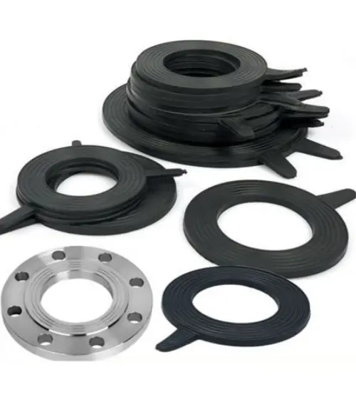
7. Flange gaskets
Improving gasket performance remains the most effective current method to enhance sealing and reduce leakage. Flange gaskets are broadly classified into metal and non-metal types.
-
Non-metallic gaskets are typically made from asbestos (historically), rubber, synthetic resins or other non-metal materials.
-
Non-metallic jacketed gaskets are non-metallic gaskets with a synthetic-resin outer jacket.
-
Semi-metallic gaskets combine metallic and non-metallic materials (e.g., spiral-wound gaskets, metal-jacketed gaskets).
Spiral-wound gaskets are made by helically winding a metal strip of V- or W-shaped cross section together with a non-metallic filler strip. They usually include:
-
an inner ring (metal ring fitted inside the spiral-wound gasket), and
-
an outer ring (metal ring on the gasket exterior).
Metal-jacketed gaskets are made from metals such as steel, aluminum, copper, nickel or Monel alloy. Metal-jacketed gaskets are especially suitable for high-temperature, high-pressure sealing locations such as heat exchangers and pressure vessels. They effectively prevent gasket disintegration and media corrosion, and they increase pressure resistance.