TPB600 Pump — Plunger Packing Replacement Illustrated Procedure
Overview
The plunger packing on a cement pump truck provides compression, sealing and isolation. Its condition determines whether the cement pump can operate normally. The 30 MPa working environment readily damages packing. Packing functions like a labyrinth: the medium is repeatedly throttled within the labyrinth to achieve sealing. Proper replacement and assembly are required for reliable performance. The HB-1402 cementing team has prepared the following replacement procedure to facilitate training, usage and standardized operation.
Tools & Safety
-
2-inch hex socket (special) wrench
-
Pry bar
-
10-lb hammer
-
Plunger wrench and plunger installation/removal tools (specialized)
-
Inlet and outlet cap removal/installation tools (specialized)
-
Valve removal tools (for valve bodies and valve springs)
-
Seal/oil-seal housing removal and installation tools
-
Packing gland / packing box removal and installation tool
-
Sandpaper for hand polishing
-
Cleaning solvents, lint-free rags, lubricants
-
Personal protective equipment (PPE)
Step-by-Step Procedure
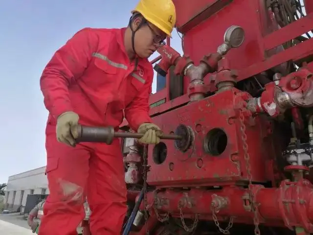
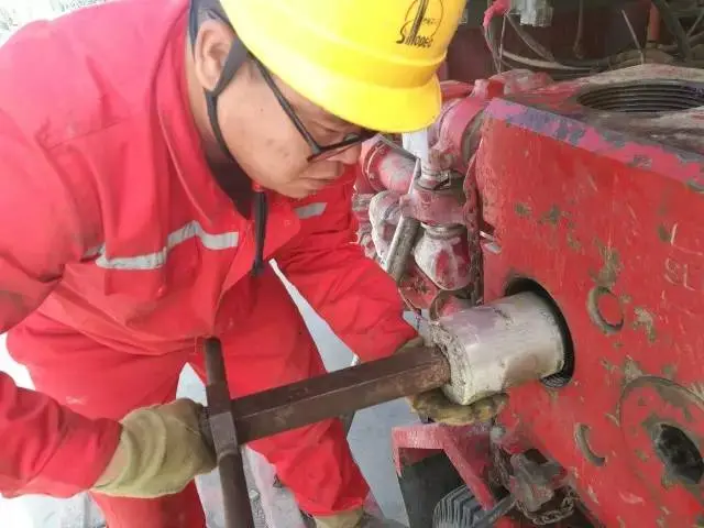
1. Loosen the threaded packing gland
Using a 2-inch hex socket (special) wrench, pry bar and a 10-lb hammer, loosen the threaded packing gland.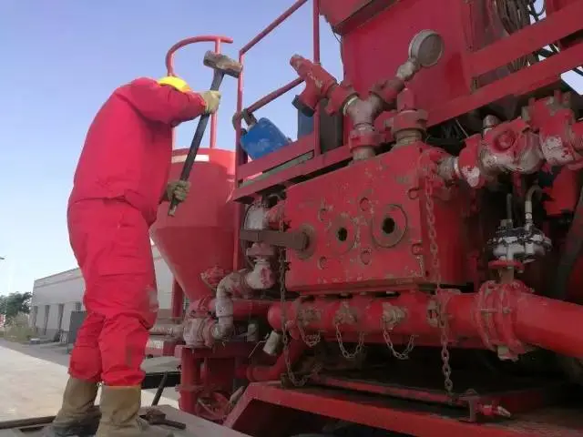
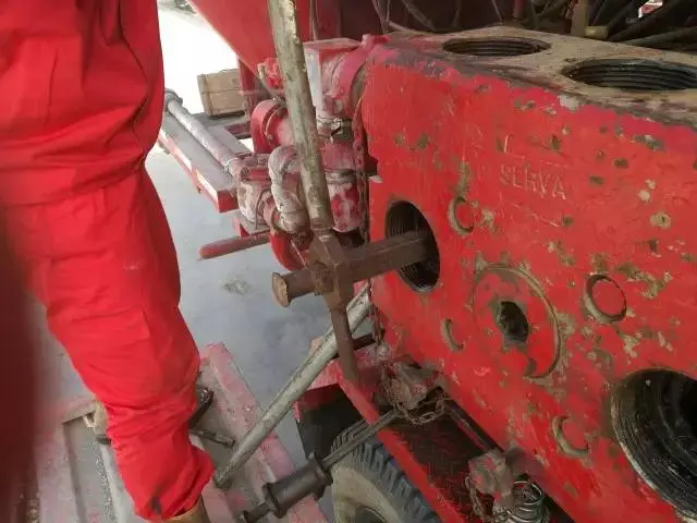
2. Remove inlet and outlet caps
Use the specialized inlet (suction) and outlet (discharge) cap removal tools to extract the caps.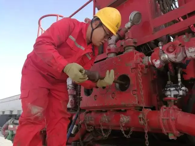
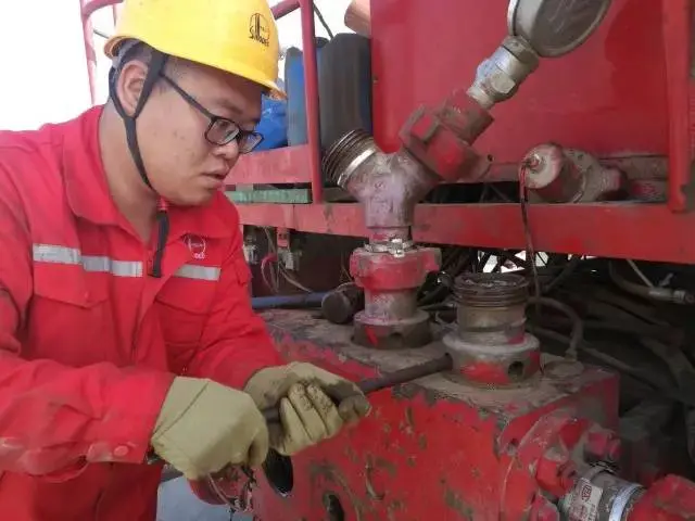
3. Remove valve assemblies
Rotate the inlet valve spring retainer about 90°, disengage it from the pump-head slot and remove it. Extract the discharge and inlet valve bodies and their valve springs from the pump head. Inspect the valve bodies and valve rubber (seats) for excessive wear or scoring; replace as required. Reinstall into the pump chamber if serviceable.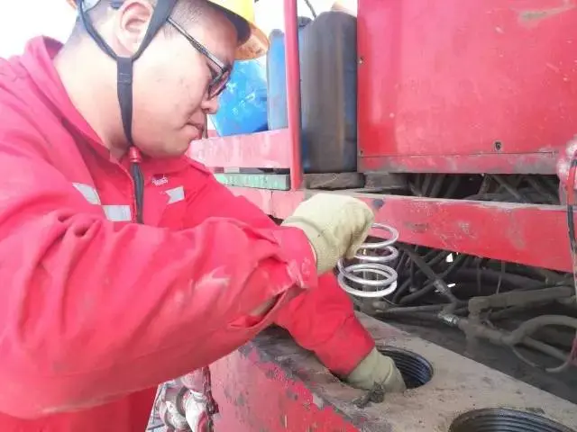
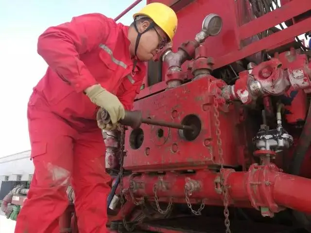
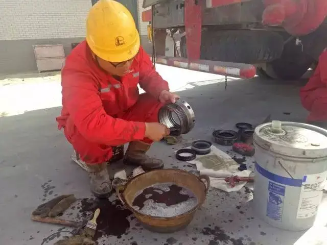
4. Remove the plungers
Using the plunger wrench, loosen the plungers at the crosshead, then remove each plunger through the pump-head inlet opening. Take care to prevent contaminants from entering the power-end components. Do not scratch or nick the plunger surfaces.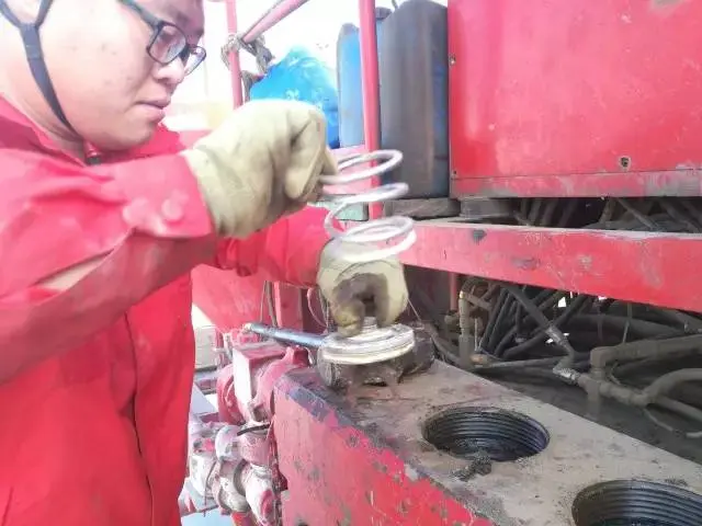
5. Remove the power-end oil-seal housing assembly
Dismount the oil-seal housing assembly on the power end.

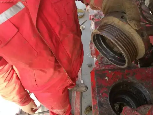
6. Remove the packing gland / packing box
Use the dedicated tool to take off the packing box.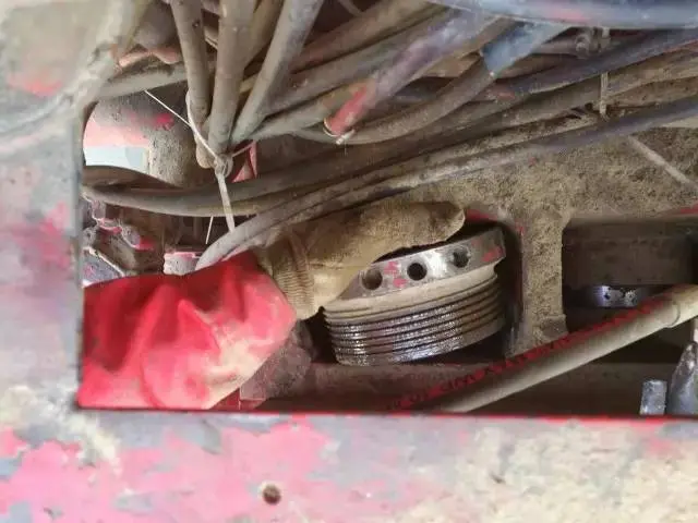
7. Clean and polish sealing cavities
Thoroughly clean the packing box and the pump-head sealing cavity. Lightly hand-polish mating surfaces with sandpaper—by hand only.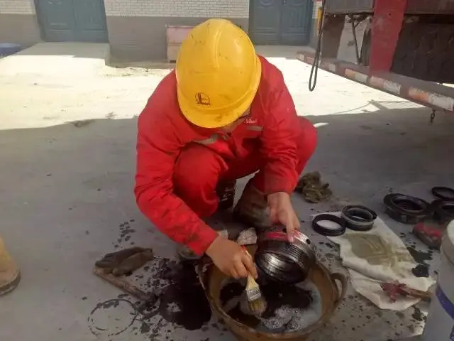
8. Assemble new packing set
With the cleaned packing oil ring and packing follower, and using new packing rings, assemble one complete packing set.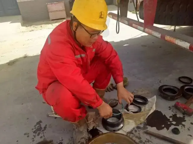
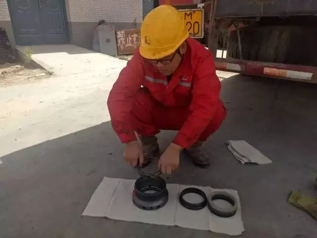
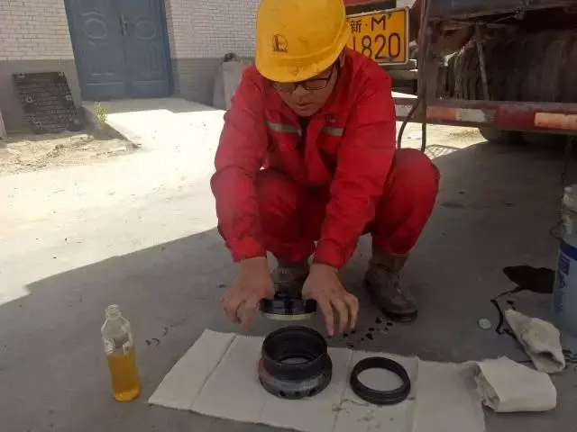

9. Install the packing box
Install the corresponding packing box and thread it up until properly secured.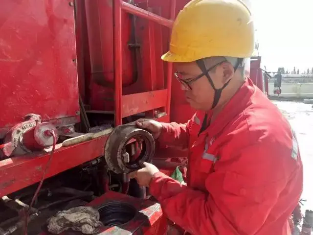
10. Reinstall the power-end oil-seal housing assembly
Reinstall the oil-seal housing assembly on the power end.
11. Refit plungers and check alignment
Apply lubricant to the exterior surface of each plunger and insert it into the packing. Using the plunger installation tool and a 10-lb hammer, gently tap the plunger into the packing so that it is aligned as closely as possible with the packing chamber axis. Continue tapping the plunger through the packing; when the plunger is nearly in contact with the crosshead connection bolt, stop. Rotate the input flange slightly—if the plunger is pushed out (indicating correct seating), tighten the connection bolt. Do not strike excessively to avoid damaging the plunger or stripping the connecting-bolt threads.
12. Reinstall caps and torque the packing gland
Install the inlet/outlet caps with the specialized tool. Install the threaded packing gland and secure it using the 2-inch hex socket (special) wrench and a 10-lb hammer.