


Product Overview
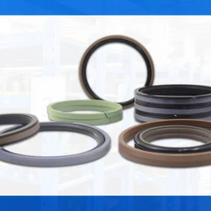
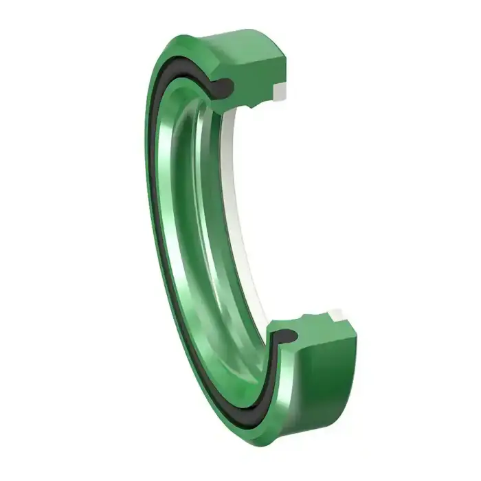
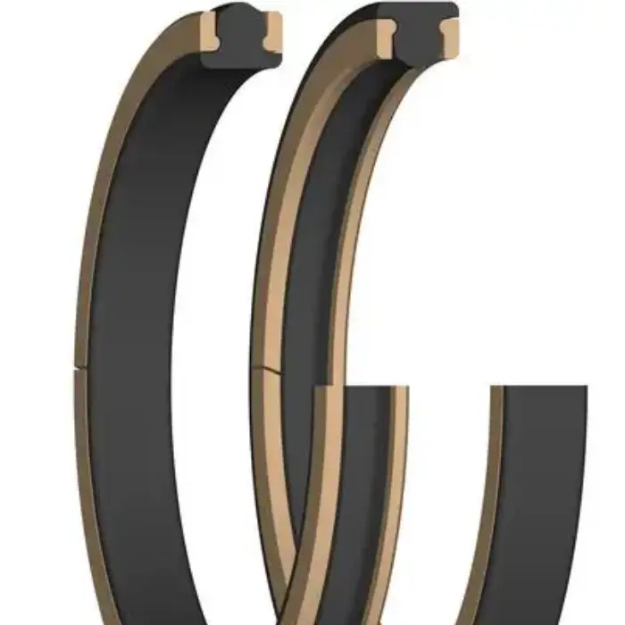
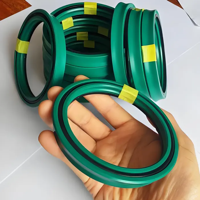
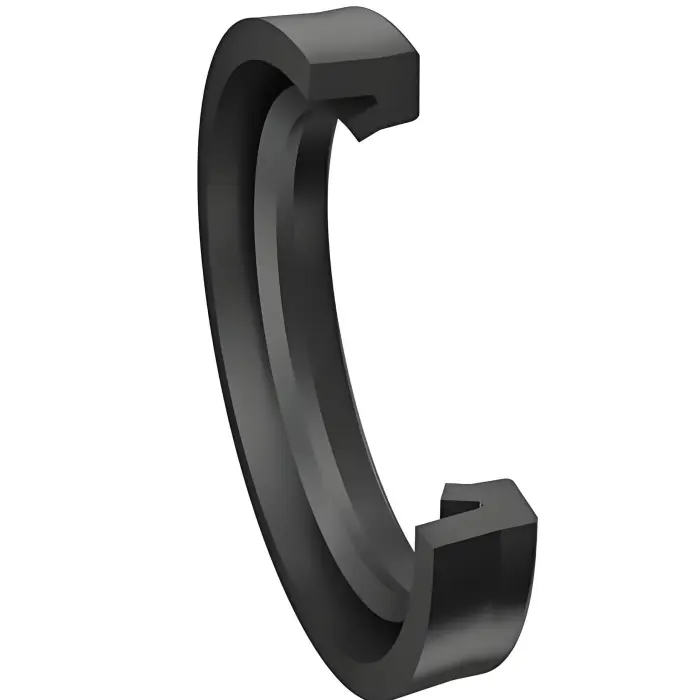
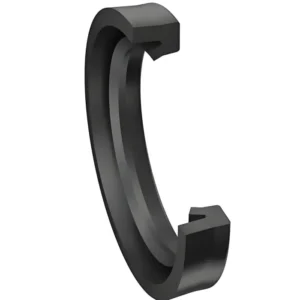
Pneumatic rod seals are designed specifically to seal reciprocating rods in air cylinders and pneumatics. Compared with hydraulic rod seals, they prioritize low friction and fast response at typical pneumatic pressures and cycle frequencies. Seal profiles include single-lip U-rings, U-cups with energizers, PTFE composite rod seals and combination rod-wiper assemblies for compact or contaminated applications.
Key Features
-
Low break-away and running friction for rapid actuation and accurate positioning.
-
Material options: polyurethane (PU) for abrasion resistance, NBR/HNBR for general purpose and oil tolerance, PTFE (and PTFE-filled) for ultra-low friction and wide temperature/chemical resistance.
-
Available as standalone rod seals, rod-wiper combinations, and integrated kits for easy replacement.
-
Compact cross-sections for short-stroke and compact cylinder designs.
Materials & Typical Performance
Common materials and selection guidance
-
Polyurethane (PU): excellent abrasion resistance and cycle life — preferred for high cycle dusty or abrasive pneumatic environments.
-
NBR / HNBR: cost-effective, good sealing for slightly contaminated or lubricated air; HNBR offers improved temperature and chemical resistance.
-
PTFE / PTFE-filled: lowest friction and best chemical/temperature range among common options; useful where stick-slip must be avoided.
Typical operating envelope (industry norms)
-
Nominal pneumatic system pressure: typical industrial pneumatic systems ≈ 6–8 bar (commonly quoted 100–200 psi class for NFPA cylinders); check cylinder rating.
-
Temperature range: elastomers commonly −40 °C to +85 °C; PTFE variants extend well beyond that in many compounds.
-
Linear speed: many pneumatic rod seals are specified for speeds up to ~1 m/s for continuous service; check profile datasheet for higher transient speeds.
-
Surface finish (rod/mating): recommend Ra ≤ 0.4–0.8 μm (16–30 μin) depending on material; smoother finishes reduce wear and leakage risk.
Applications
-
Industrial pneumatic cylinders in automation and packaging equipment
-
Pick-and-place actuators and robot end-effectors
-
Compact cylinders in automotive assembly and material handling
-
Air-powered presses, clamps, and grippers
(Include aliases naturally: “rod sealing ring”, “air cylinder rod seal”, “pneumatic cylinder rod seal”.)
Technical specifications (typical ranges)
| Parameter | Typical value / range |
|---|---|
| Bore / rod diameter availability | commonly stocked OD/ID diameters covering rod Ø 4 mm — 250 mm for standard profiles (many profiles supplied for NFPA/ISO cylinder sizes). |
| Recommended pressure (pneumatic service) | Typical design for air service ≤ 0.6–1.0 MPa (6–10 bar / ~90–150 psi) depending on seal profile and gland design; verify per profile. |
| Temperature range | Elastomers −40 °C to +85 °C; PTFE options extend wider per compound. |
| Linear speed | Up to ~1.0 m/s continuous for common profiles; verify for specific PTFE/spring-energized seals. |
| Surface finish (rod) | Ra 0.4 µm (16 µin) recommended for PTFE; Ra ≤ 0.8 µm for elastomers. |
Common sizes & stock examples
-
Metric stock examples: rod seal rings for rod Ø: 6 mm, 8 mm, 10 mm, 12 mm, 16 mm, 20 mm, 25 mm, 32 mm, 40 mm, 50 mm, 63 mm, 80 mm, 100 mm, 125 mm, 160 mm, 200 mm, 250 mm.
-
Standard NFPA/ISO cylinder sizes: 1.5″, 2″, 2.5″, 3.25″, 4″, 5″, 6″ (rod/gland kits available to match common cylinder families).
-
Typical cross-sections (examples): 25×33×6 mm combination rod-seal/wiper; 22×28×7 mm U-cup; custom molded sizes available on request.
Note: Always confirm groove geometry and gland depth before ordering. We supply installation drawings and groove templates for each profile.
Why choose these pneumatic rod seals (advantages)
-
Low friction, high responsiveness — faster cycle times and improved positional accuracy.
-
Long service life in abrasive air environments (PU compounds offer superior abrasion resistance).
-
Integrated rod-wiper options — reduce contamination ingress and extend system life.
-
Wide material selection — match to lubrication conditions, temperature and chemical exposure.
Pneumatic Rod Seal vs Hydraulic Rod Seal
| Characteristic | Pneumatic rod seal | Hydraulic rod seal |
|---|---|---|
| Primary sealed medium | Compressed air or gaseous media | Hydraulic oil / incompressible fluids |
| Typical pressure design | Lower pressure design focused on low friction and fast cycles (pneumatic ranges ~6–10 bar typical). | High-pressure design (hydraulic seals rated for tens to hundreds of bar; extrusion resistance prioritized). |
| Material priorities | Low friction, abrasion resistance, contamination tolerance (PU, NBR, PTFE) | High extrusion resistance, reinforced PTFE, metal-backed or composite constructions |
| Typical applications | Fast-cycling air cylinders, utilities with frequent starts/stops | Heavy loads, slow/continuous hydraulic actuators |
| Installation concerns | Groove tolerances and surface finish to minimize friction and wear | Groove design to prevent extrusion and maintain sealing at high pressure |
Design implication: Do not substitute pneumatic-optimized rod seals into a hydraulic system — hydraulic pressures and fluid chemistry require different profiles and anti-extrusion measures.
Installation & maintenance notes
-
Verify rod hardness (recommended > 45 HRC for high wear) and finish; remove burrs and plating irregularities.
-
Observe recommended groove dimensions and radial clearance per profile drawing; incorrect depth affects extrusion and leakage.
-
Use light assembly lubricant compatible with the medium; where oil contamination is present, prefer NBR/HNBR energizers.
-
For exposed rods or contaminated environments use rod-wiper combinations or separate scrape seals to protect the rod seal.
Downloads
E-E-T-A
-
Experience: Decades supplying OEM pneumatic seals and aftermarket kits for automation and industrial pneumatics.
-
Expertise: In-house application engineering validates gland design, selects appropriate compound, and predicts wear life under specified cycle rates.
-
Authoritativeness: Standardized profile drawings, ISO/NFPA cylinder match guides and test reports available on request.
-
Trustworthiness: Lot traceability, batch inspection records, and dimensional reports accompany production runs — sample testing available before production.
FAQ
Q — What information do you need for a firm quotation?
A — Provide rod diameter, gland/groove drawing (or cylinder model), expected operating pressure, temperature range, speed, media (dry air, lubricated air), and annual cycle estimate. Quantity and delivery location complete the RFQ.
Q — Can you supply rod seals as pre-assembled piston/rod kits?
A — Yes. We supply full rod kits (rod seal, wiper, backup) and piston kits to customer specifications with part-numbered packaging for production lines.
Q — What are lead times and MOQ for custom sizes?
A — Standard stocked sizes: 1–2 weeks. Custom molded or special compounds: typical lead time 4–8 weeks, MOQ depends on profile/tooling — we provide exact figures with a technical quote.
Q — How do I avoid stick-slip in my pneumatic cylinder?
A — Choose PTFE or PTFE-filled rod seals with a compatible energizer and ensure correct surface finish and lubrication practice. We will advise the optimal compound based on cycle profile.
Call to Action / Contact
Hengshui Aohong— Mechanical Seals Division
-
Email: sales@aohongglobal.com (for datasheet requests and fast quotes)
-
Phone: +(86) 153 7318 1024 (please replace with your official number)